Raspberry Pi PWM Fan Control
Goal
In this tutorial, we’re gonna build a PCB to control a fan to cool the CPU of a Raspberry Pi board. The reason we’re gonna need an extra bit of hardware is the Pi’s GPIO can’t handle sufficient currents.
Find out more about the Raspberry Pi’s GPIO in the documentation.
In electronics, we ususally separate high power and low power circuits. A low power logic circuit like a microcontroller typically controls a higher power circuit, like a motor driver. The Pi’s GPIO acts as a low power circuit but, the Pi can also handle slightly higher currents on other pins known as supply pins: 5 V or 3.3 V. Unlike the GPIO, those can’t be turned on or off: they’re always on. They can handle currents sufficient for our 5 V 0.16 A fan, but we can’t control them. We would therefore need some kind of switch that the GPIO can control. When closed, the fan would be connected to +5 V on one side and to the ground (GND) on the other side and would thus rotate. Turns out we’re lucky! This is exactly what a transistor does.
It’s important to understand the Pi, with its USB power supply, could never drive a big electric motor or some serious actuator, but, the fans we’re talking about are very small and have a very limited torque: they won’t require currents as high as, say, a small robot’s motor.
Parts choice
To get started, we’re gonna need to pick a transistor. This might seem a bit overwhelming at first as they are literally thousands of suitable options out there, but we’re gonna limit out scope to something common and cheap we can solder ourselves.
I went for a 2N2222A transistor in a TO-92 package. What’s that beast may you ask? Well, that’s pretty simple. This is an NPN transistor we’re gonna use as a switch. The first thing we need to make sure of is it can drive sufficient currents, we definitely wouldn’t want to blow it when using our fan. According to the transistor’s datasheet, it’s suited for 500 mA applications which is more than enough in our case. We could pick a transistor suited for smaller currents but that won’t make a huge difference in price and it’s always nice to have some margin allowing to use the PCB in another context.
At this point, we’re almost done. We’re still gonna need two extra components: a diode and a resistor. Don’t worry I’ll explain!
The main objective of our setup is to control a fan, by opening and closing a switch. Opening the switch does not immediately stop current in the motor windings. The motor acts as an inductor and this causes current to continue to flow when the switch is opened suddenly. Charge builds up on what was the negative terminal of the motor which may cause damage! A reverse current surge may occur or, in extreme cases, an arc may form across the switch resulting in a discharge to ground. We definitely want to avoid this and need a way to safely dissipate electrical energy when the switch is opened. The addition of a diode in parallel with the motor (usually refered to as flyback or freewheeling diode) creates a way for stored energy to dissipate.
The last bit we’ll need is far simpler: adding a series resistor between the control input and the base of the transistor limits current into the base. The type of transistor we’re using typically accepts 0.6 V to turn on — more voltage means more current.
- Diode: 1N4001 (DO214AC)
- Transistor: 2N2222A (TO-92)
- Resistor: 1k (1206)
Schematics
We’re all set to produce some schematics at this point. Here’s the outcome:
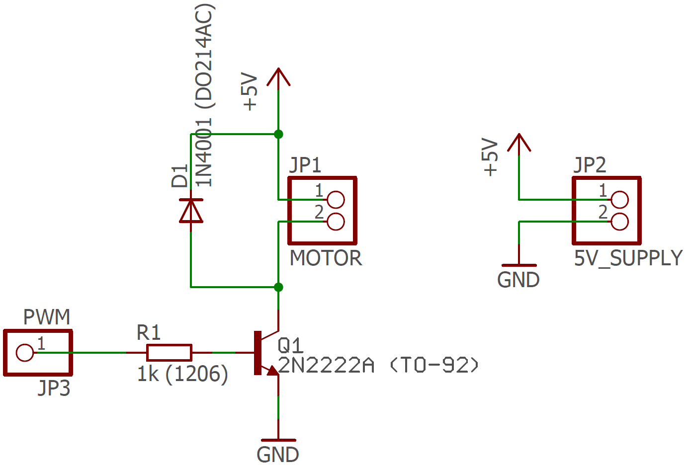
I’ve been using EAGLE with some nice libraries to produce those. The SCH file is available in this archive.
Layout
This is a very simple monolayer layout. When routing your board, it’s important to respect the manufaturer’s design rules. I’m personally using DirtyPCBs which is cheap and overall reliable, especially for boards that simple. If you’re using EAGLE, grab their DRU file here and run a DRU check.
Here’s the outcome:
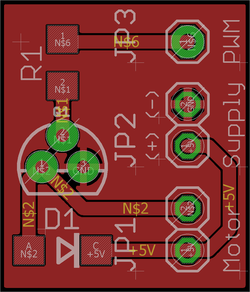
- I used 0.8128 mm traces as we’re not really restricted here.
- To make it nice and user-friendly, I added some informative labels on the
tPlacelayer. - The board will be about 1.5 cm².
The layout BRD file is available in this archive as well.
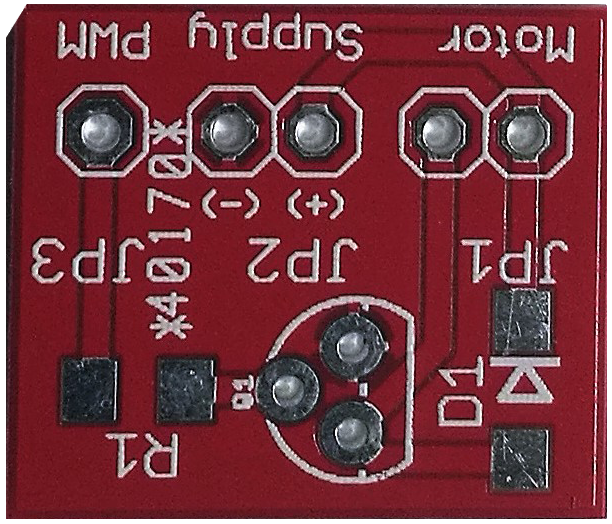
Production
This is what the PCBs I received look like. They’re pretty clean considering I paid about $10 excluding shipping.
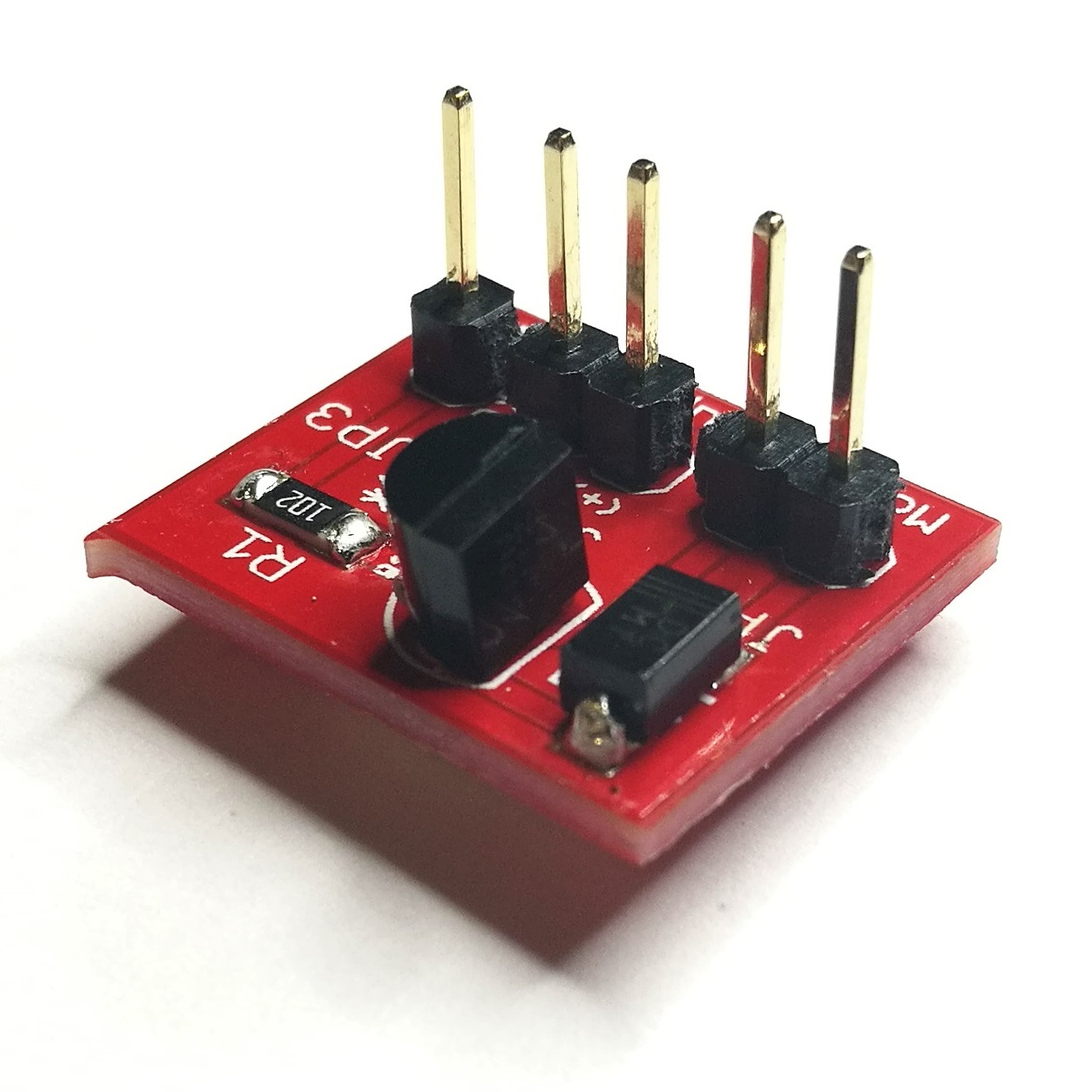
Here’s what the outcome looks like. All components fit nicely, just like expected. Make sure to bend the transistor’s pins so that it’s touching the board.
Scripts
It’s now time to test the thing. Let’s wire it and run some simple Python script to turn the fan on and off. We’ll deal with PWM later.
#!/usr/bin/env python3

import os
from time import sleep
import signal
import sys
import RPi.GPIO as GPIO

pin = 18 # the pin ID, edit here to change it
maximum_temperature = 40 # the maximum temperature in Celsius after which we trigger the fan

def setup():
    GPIO.setmode(GPIO.BCM)
    GPIO.setup(pin, GPIO.OUT)
    GPIO.setwarnings(False)
    return()

def get_cpu_temperature():
    res = os.popen(‘vcgencmd measure_temp’).readline()
    temp =(res.replace(“temp=”,””).replace(“’C\n”,””))
    return temp

def get_temperature():
    CPU_temp = float(get_cpu_temperature())
    if CPU_temp > maximum_temperature:
        fan_on()
    else:
        fan_off()
    return()

def fan_on():
    set_pin(True)
    return()

def fan_off():
    set_pin(False)
    return()

def set_pin(mode): # useful if you want to add logging
    GPIO.output(pin, mode)
    return()

try:
    setup()
    while True:
        get_temperature()
    sleep(5) # read the temperature every 5 sec, increase or decrease this limit if you want
except KeyboardInterrupt: # Ctrl+C keyboard interrupt
    GPIO.cleanup() # resets all GPIO ports
Everything works just as planned! The last thing we want to be able to do is change the speed of the fan depending on the CPU’s temperature using PWM. That will be our final script.
#!/usr/bin/env python3

import os
from time import sleep
import signal
import sys
import RPi.GPIO as GPIO


fan_pin = 17 # fan pin ID
desired_temperature = 45 # maximum temperature in Celsius after which fan is triggered

fan_speed = 100
sum = 0
p_temp = 15
i_temp = 0.4

def get_cpu_temperature():
    res = os.popen('vcgencmd measure_temp').readline()
    temp =(res.replace("temp=","").replace("'C\n",""))
    return temp

def fan_off():
    PWMControl.ChangeDutyCycle(0) # switch fan off
    return()

def handle_fan():
    global fan_speed,sum
    actual_temperature = float(get_cpu_temperature())
    diff = actual_temperature - desired_temperature
    sum = sum + diff
    pDiff = diff * p_temp
    iDiff = sum * i_temp
    fan_speed = pDiff + iDiff
    if fan_speed > 100:
        fan_speed = 100
    if fan_speed < 15:
        fan_speed = 0
    if sum > 100:
        sum = 100
    if sum < -100:
        sum = -100
    PWMControl.ChangeDutyCycle(fan_speed)
    return()

def set_pin(mode): # useful to add logging
    GPIO.output(fan_pin, mode)
    return()
try:
    GPIO.setwarnings(False)
    GPIO.setmode(GPIO.BCM)
    GPIO.setup(fan_pin, GPIO.OUT)
    PWMControl = GPIO.PWM(fan_pin,50)
    PWMControl.start(50)
    GPIO.setwarnings(False)
    fan_off()
    while True:
        handle_fan()
        sleep(1) # read the temperature every 5 seconds
except KeyboardInterrupt: # Ctrl+C keyboard interrupt
    fan_off()
    GPIO.cleanup() # resets all GPIO ports
This is it! We’re done with this project. Feel free to customize the scripts in any way you want.